See 'Perfornfing Routine Maintenance' manual. Do not run the furnace without. Page 49 After the hot surface igniter is heated for about 20 seconds, the Al1291 gas valve pernfits to ON tion and a time delay of up to 60 sec, the furnace blower start. Control makes the necessary at either the low- or high-heat.
PLEASE DO NOT ATTEMPT THIS IF DO NOT KNOW WHAT YOU'RE DOING. Your furnace control system is a critical safety system. If you repair or install it incorrectly or damage the system, it can burn your home down or cause a gas leak with people inside, causing severe injury and/or death. I cannot emphasize this enough. Be careful, PLEASE! The following information is for informational purposes only.
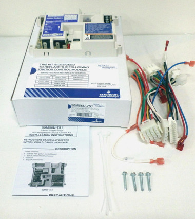
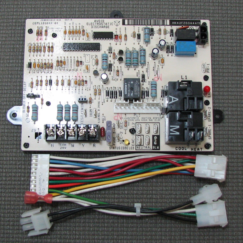
Hk42fz011 wiring diagram – What’s Wiring Diagram? A wiring diagram is a type of schematic which makes use of abstract photographic symbols to reveal all the interconnections of elements in a system. Wiring layouts are comprised of two points: symbols that stand for the elements in the circuit, as well as lines that represent the links in. Carrier HK42FZ011 Integrated Furnace Control Board. Carrier HK42FZ081 Integrated Furnace Control Board. Customers Also Viewed. Carrier HC23CE116 Draft Inducer Motor. Carrier HD44AE116 ECM 2.3 Blower Motor Assembly.
For those people who would like to replace rather than repair their furnace board, I believe something like this should work: HK42FZ007.
The non-condensing forced air gas furnace in our home had been having intermittent trouble starting up. The furnace brand seems to be 'Night and Day' and the model is Plus 80. The normal startup sequence is something like this:
- Inducer fan starts
- Hot surface igniter glows
- Gas turns on
- House blower turns on
After doing some initial debugging and internet research, I learned that our furnace uses a Carrier HK42FZ007 Furnace Control Board. This board is similar to a number of control boards such as HK42FZ004, HK42FZ008, HK42FZ009, and HK42FZ011. From my internet research, it seems that all these boards except the newest HK42FZ011 have a design flaw that causes one or two of the power resistor solder points to crack, leading to an intermittent connection. The symptoms are intermitted inducer behavior much like what our furnace was doing.
I pulled the board and took a peek. Here are some photos from this project:
The control board inside the furnace, showing wires connection points.
The control board inside the furnace, more wires.

The control board inside the furnace, even more wires.
To remove the board, there were two sheet metal screws holding the black case to the furnace. Make sure to record which wires go to which terminals before removing the board; I took detailed photos above.
The control board is out of the furnace.
Closeup of the control board box.
Closeup of the control board box another angle.

Back of the control board box.
To remove the board from the case, gently pry the back off. There are clips all around the edge, and if you are careful, you can remove the back without damaging the case. Inside, you will find the circuit board:
Hk42fz011 Manual 2016
Circuit board front. Click for a larger version.
Circuit board back. Click for a larger version.
Hk42fz011 Manual Pdf
After some close inspection, I found cracks in the solder on R33 and R34, the large resistors in the board's cutout. Here's a closeup of the cracking. You can see the cracks on the two solder points on the left side of the image:
Cracked solder on the left two solder points.
To repair this problem, I used my soldering iron and reflowed the four solder points on those two resistors and added some more solder to the points also. Here's a photo of the repaired board. It's hard to see but the solder points are nice and solid now.
Repaired solder cracks.
Hk42fz011 Manual Online
I reinstalled the board and ran the control board's self-test. Everything seemed ok, so I fired up the furnace, and I have not heard the inducer hiccup for more than 6 hours now. I'm pretty certain the problem is fixed now.
I hope this is helpful for people out there facing a similar problem.